
The combination of the Dynojet PVCX as a data collector and the Dynojet Power Core Software Suite (PCSS) for a powerful engine tuning combination. This post will deal with the steps necessary to begin collecting (log) data that is useful for correcting the tune.djt file you are currently have flashed in the ECU.
Since the first method we will discuss uses the factory installed narrowband o2 sensors we need to understand both the positives and limitations of this method.
On the positive side of the equation:
- By using the narrowband, there is no additional hardware to purchase and install on your bike.
- Narrowband sensors are very fast responding compared to wideband sensors.
- The ECM reads and provides corrections based on the narrowband data...we will too.
On the limitation side of the equation:
- The closed-loop area that the narrowband's operate in does not cover the complete load versus RPM table.
- Since we are using the calculated error channels of the Short & Long Term Fuel Trims derived from the narrowband sensor, which only indicates Rich, Lean, and Stoic conditions, we are estimating actual AFR instead of direct measurement of AFR.
Let's startup Dynojet's Power Core Software Suite. If you do not have this program installed on your Windows computer, then go to Dynojet's website's support page for the PV3 and download and install the current Dynojet Power Core Software Suite. This software supports both the PVCX and PV3 DJT and CXL/WP8 files from recording logs.
Once installed, double click on the desktop Dynojet Power Core icon to start the Application Launcher:

(Click on image to expand)
The next step on a NEW INSTALLATION is to verify that software will check and update to the newest version when first started. Under the Tools menu, select the Options item.

(Click on image to expand)
This is the screen shows the boxes you want checked so that the software will update to the newest Beta version. Note, once you select and apply these boxes. Close and restart the Power Core Application Launcher so it can verify or upload the newest version.

(Click on image to expand)
Once you are sure your Dynojet Power Core Software Suite is at Version: 2.4.2 or higher, select the C3 module. This is the core module we will use to view, run equations, and make modifications to our Tune.

(Click on image to expand)
When C3 starts up, you are presented with this screen:

(Click on image to expand)
Select Open File icon to open a Tune file, a custom tune will always have the DJT extension and a Polaris Factory Calibration will have an STK extension:

(Click on image to expand)
Navigate to the folder that you created with the Stock.STK file and Tune.DJT file you wish to open. In this example, I would select the KCV4FIN.DJT file to view and modify my currently Tune. However, I am going to select the B8F0A6B0.STK which is my stock file for my bike. Any file with the STK extension is a Stock factory calibration, which you can modify and save as a DJT file.
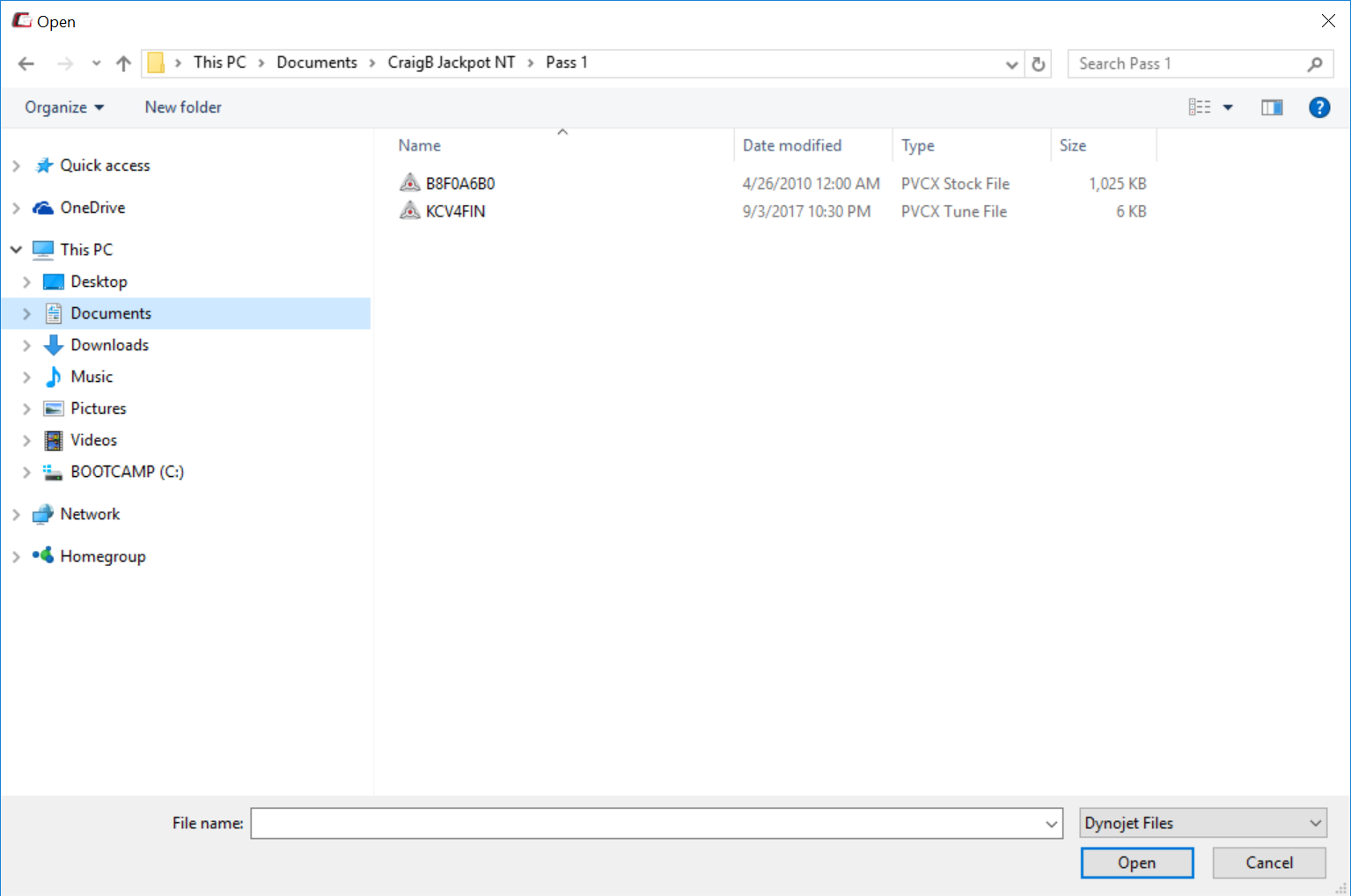
(Click on image to expand)
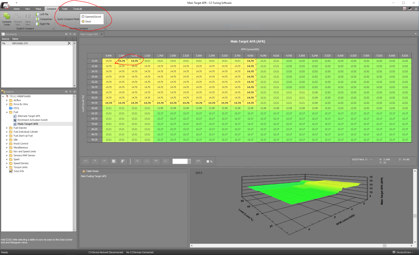
C3 displays the file and a tree view, which is how we navigate through the Tune tables and parameters. I've highlighted the tree view.

Select the Fuel folder and then click on Target AFR so that table is displayed.

(Click on image to expand)
Now we are at the point to start discussing the tuning process with narrowband sensors.
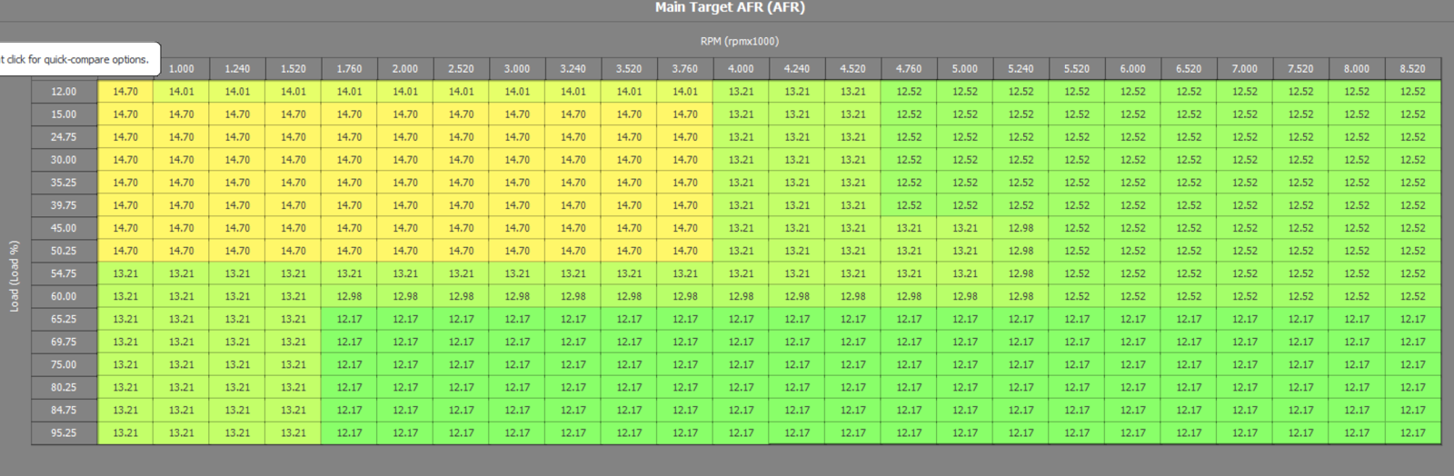
The first limitation is not as bad as it first appears. If you look at a typical Target AFR in the Fuel table of the tune calibration, you will notice 14.7 (the value that places the ECM into closed-loop operation) starts at the lowest RPM/Load cell and extends to 3750k and 50.25% load. This represents at least 95% of normal operating range for most folks.
It is this fact that makes narrowband tuning viable for folks wishing to improve their overall engine performance, both from performance and MPG perspective.
Here is a view of the closed-loop operating zone of a factory stock file. Closed-loop extends to 50% and under 4k RPM.

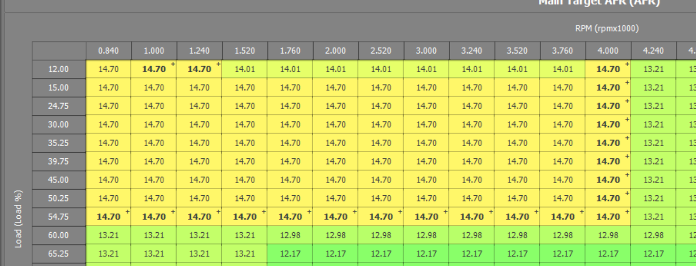
I usually extend the closed-loop to 54.75% load and 4k RPM and higher for tuning purposes. But it is not necessary to change this table until you are comfortable with the tuning process and have a good feel how your engine is responding.

(Click on image to expand)
I usually extend the closed-loop to 54.75% load and 4k RPM and higher for tuning purposes. But it is not necessary to change this table until you are comfortable with the tuning process and have a good feel how your engine is responding.
(Click on image to expand)
- A word of caution...why not place the complete table in closed-loop operation while tuning? Because your engine will run excessively lean in high load/RPM operating conditions and will result in either poorly performing engine at best and a damaged engine at worse. There is no upside on doing this. NEVER DO THIS.
Note the "+" sign in the upper cell in the cells we changed. This represents one of two conditions: The value is different then the saved value, or the value is different then the stock value. You set this up by selecting the Compare menu item and check the approprate box.
FEATURE ALERT: A cool feature of C3 is the ability to view this changed value and difference easily by pressing the ALT button while hovering over the cell.

Once you set or verify that your Target AFR is setup for good closed-loop area of operation, it is time to save this file. Select the Save As icon:

Rename the file something useful like version number and place it in a folder that represents your base beginning tune.

I usually create a folder with my name: "Craig's Custom Tune" and within that file start creating sub-folders that represent each tuning step. So for the first tune, it goes into a folder named "Pass 1". I also put the stock.stk file within that folder as well.
FEATURE ALERT: A cool feature of C3 is the ability to view this changed value and difference easily by pressing the ALT button while hovering over the cell.
(Click on image to expand)
Once you set or verify that your Target AFR is setup for good closed-loop area of operation, it is time to save this file. Select the Save As icon:

(Click on image to expand)
Rename the file something useful like version number and place it in a folder that represents your base beginning tune.

(Click on image to expand)
I usually create a folder with my name: "Craig's Custom Tune" and within that file start creating sub-folders that represent each tuning step. So for the first tune, it goes into a folder named "Pass 1". I also put the stock.stk file within that folder as well.
There are other tables that can be changed for the user's preferences, i.e. Drive By Wire, Rev Limit, etc. But it is not necessary for tuning purposes. I will discuss that in another post.
After changing your Target AFR table and saving this custom file, you are now ready to copy this file to your PVCX/PV3 and flash your ECM to begin the tuning process!
Connect your PVCX/PV3 to your computer through the USB port and open File Explorer and navigate to your folder that has the tune.djt you just modified.
Notice the PowerVision disk has been mounted and displays on the tree directory on the left.

(Click on image to expand)
Copy the modified Tune.djt to your PVCX/PV3 PowerVision disk.

(Click on image to expand)
You can drag or copy & paste, whichever way you prefer to do it. Once you have copied the Tune.djt file to the PVCX, Double click on the PowerVision icon and open it in File Explorer.

(Click on image to expand)
Verify the Tune.djt has been copied. Notice the three files on my PVCX/PV3, My stock.STK file has to be always present, the new tune.djt file, which will be flashed, and lastly the PV_Info.txt file that has key information about your ECM's Tune CMP and Checksum.
Once you are happy that the Tune.djt file has been successfully copied, you are now ready to Flash this to your ECM.
NOTE: The factory STK naming convention is strange at first. Looking at the directory below, there are 4 log files that have the WP8 extension, 1 tune file with the DJT extension, and 1 Factory Stock Calibration with the STK extension. This STK file is named VMB8F0A6B0, which is the Tune CMP. In this case, Polaris used this Tune CMP for years 2014 through 2016 TS111 engines. If you are logging with the PVCX, its logs will have the CXL extension.
(Click on image to expand)
What is not shown is the Checksum some of you might have heard on the forum. The STK's checksum determines which stage or modifications Polaris has applied to the Tune CMP. It is displayed in the File Explorer by selecting the following under View menu (Preview Pane):
(Click on image to expand)
Once you do this, highlight the STK file and you will find the Checksum of the file in the preview window:
(Click on image to expand)
(Click on image to expand)
The Checksum for the STK file is: 7B1784CB. This happens to be the stage 2 factory calibration.
Why is this important? The PV3/PVCX will only display compatible tunes to flash to the ECU. Compatible tunes are tunes that have been built on the same Tune CMP and Checksum that has been flashed to the ECU by the Polaris Digital Wrench tool at the dealership.
The PV_Info.txt file on your PV3/PVCX contains important information on your device GUID, which is an unique id for your PV3/PVCX. It also has the Tune CMP and Checksum that is currently flashed to your ECU.
Here is a portion of my PV_Info.txt file from my PVCX:
Device Information:
FW Version: 2.3
FW Build: 6499.19303
Serial: PV00017759
GUID: 0d00801b-0083-aefa-ec42-c257c52000f5
Paired: 1
Pair Version: 4
Paired ECU: 000350490923
Paired Vehicle: 56KTRAAA6G3337341
Paired Tune Compat: VMB8F0A6B0
Paired Checksum Compat: 9586AEB4
Version: 1
Vehicle Model: NGRABABCG
ECU Model: F00HM00186
ECU SN: 000350490923
ECU VIN: 56KTRAAA6G3337341
ECU Manu PN: 4014125
Veh Manu PN: 4016671
ECU Tune Compat: VMB8F0A6B0
ECU SW Version ID: 10SW011972
ECU Patch Num: 4016672
ECU Checksum: 9586AEB4
The top line has the current Firmware build. For the PVCX, this is the current and last build since Dynojet no longer supports this device. The PV3 has the same structure for its PV_Info.txt file too.
The Tune CMP is: VMB8F0A6B0 and the Checksum currently in the ECU is: 9586AEB4. Notice it has a Paired Tune CMP and Checksum as well as the ECU Tune CMP and Checksum. Make sure your bike is on when you force the PVCX or PV3 to capture the newest PV_Info.txt. It is the ECU information you want.
In the above example, my bike was a 2016 and was flashed with the stock factory calibration (9586AEB4)