.feed-links {display:none !important;}

Friday, June 24, 2022

Practice Example with Files

You can download a complete tune cycle example and follow along with the following video.  The goal is to start off with the supplied base tune, complete each simulated recording log cycles, make corrections starting with the base tune.  When the 7th cycle is completed you can compare your version 7 tune with my supplied example version 7 tune and if they match, you have successfully completed this first tutorial!


Here is the example folder to download to your computer.  It is large, so it will take a minute or two to download.  Just save it to a good location on your computer so you can open the files with Power Core's C3 and Data Center modules.  You will also need the VE/IPW Comp equation found here if you have not downloaded it already.


Here is the video that demonstrates by going through the complete tutorial with the final versions compared to show they are identical.  It is about 16 minutes long, I encourage you to go through this exercise to gain confidence in your tune corrections.

Tutorial Example


If you do not get the same results as the provided version 7, just start over.  If they are slightly off, check to make sure your Power Core Application Launcher Option settings for the Pressure channel is set to kPa and not Inches of Mercury.


Saturday, June 18, 2022

Additional Fuel Tables

There are two additional fuel tables under the Fuel Folder of your tune named Injector Compensation Factor - Front & Rear.  These tables have very little affect on the fuel balance and I mostly ignore them. In most factory calibrations (STK files), these tables are set to 1.00 in all cells.  Some STK files do have these tables corrected.  You can choose to do correct them or leave them alone and only work on the VE and IPW Comp Tables.

The procedure is exactly the same as if you are correcting the VE & IPW Comp Tables as shown in the previous videos.  But instead of correcting the VE & IPW Comp Tables, we will correct the VE & ICF Tables.  After you have corrected your VE & IPW Comp Tables, take additional logs and apply this VE & ICF EQUATION in Tune Lab to make corrections to the VE & ICF Table.

You can choose to expand the Target AFR, but I would not waste the time.  I would keep the Target AFR as your finalized tunes has it set and record logs, correct with the above equation, flash, and run/log again.  Do this until you there is very little percent difference between tunes.


Fine Tuning - Correcting VE and Injector Compensation Factor Front & Rear Tables


Friday, June 17, 2022

Finalizing Fuel Corrections

 Here is the part 2 of making fuel corrections to the VE and IPW Comp Tables.  The goal is to achieve less than 5% difference between last tune and corrected tune in the higher RPM and Load regions.  In the case of the TS111 & TS116 engines, that would be cells higher than 3.75 RPM in the VE table.  The IPW Comp tables should be less than 1% difference, they dial in very well due to the using the mean in the calculations during correction.

For Scout and FTR-1200, your would want the cells above the normal RPM range for your STK file.  In the case of the examples in previous video, the Scout would be 5k RPM and above and the FTR-1200 would be 6k and above.

Once your VE is less than 5% (I like to go less than 3%), then you should reset the Target AFR to nominal and safe values.  One you reset the Target AFR, your power-band will be restore and you can hit it as hard as you like.

The goal at this point is to continue with the cycle of tune, record logs, correct tune with logs, save as new version and repeat. As you record the logs, the operation range you are concerned about is the idle through 3.75k for the TS111/TS116, idle through 5k RPM for the Scout, and idle through 6k RPM for the FTR-1200.  Ultimately you are trying to get the normal operating range as smooth and balanced as possible.  This usually takes 4 to 5 additional cycles, though it really does not have to stop with that.  Since you now know how to tune and have the tools to do it, continue until you are happy with the results.  Just keep in-mind that gasoline quality and environmental conditions might have a higher influence on the tune than actual error.  This is the whole purpose of fuel trims in the ECU, too compensate for these variables. 

It is always beneficial, once you are in the finalization of fuel corrections, to put on several hundred miles or more before you record additional logs.  The mileage does not need to be done all at once.  This is to allow the long term fuel trims (LTFTs) to become active.  The LTFTs do not reset after each engine start, but rather keep a running average of each cell's nominal correction needed so the ECU can be more accurate when calculating the fuel for the 14.7:1 Target AFR.  This is basically all we are doing with our tuning....getting the fuel tables more accurate to lesson the amount of fuel trims the ECU needs to apply.

Finalizing Fuel Corrections (Part 2)


Thursday, June 16, 2022

Important Notes on Expanded Target AFR Tuning

 Important notes on how to log when you have expanded the operation range

When the Target AFR has been expanded to the full RPM and most if not all of the load range, care must be taken to ensure you do not damage your engine.  Here are some instructions on the best way to get data as well as very important notes on the Target AFR for tuning. 

No drag racing while we are tuning with expanded Target AFR Table!


When expanding the Target AFR's closed-loop operation to almost all of the operating range for tuning.  What this means is you are lean in the higher RPM/Load ranges so your powerband will be greatly diminished.  However, this is necessary to tune in those areas.  With this in mind, it is very important not to wack your throttle wide open, but instead make nice slow roll-ons allowing giving the ECU the time it needs to correct the fuel trims.

Moving forward, it is important to try to hit as many load and RPM combinations as possible.  I like to slowly build RPM's in 1st and 2nd gear to 5k to hit the high end.  I find 25 mph flat roads and get into 5 and 6th gears to hit the low RPM range.  I find parking lots that I can ride in 1st and 2nd gear for the low range as well.  Mountains and hills are good to go into one gear higher then normal to load down the engine.

When merging onto interstate, I like to wind up in 3rd gear until 5k (about 80 mph) to sweep those ranges as well.  Just be safe, but have fun with the tuning process.  

How to get the best data:

There are two methods for recording good logs for use in tuning your engine.
First method:

If you are up to it, you need to pick a route of about 35 minutes that offers opportunity for different load and RPM ranges.  Hills and dips, straightaways, etc.  If you do not have this, then try to load the bike under different ways by taking off in 2nd gear a couple of times, up-shift to higher gear then you normally would, even get in 5th gear and lightly apply the rear brake while maintaining the same RPM with the throttle (do not do that often and do not over heat brakes).  Rev your engine up close to rev limit when in 1st gear and 2nd gear (up shift after rev high).  But, do not be rapid on the throttle, the key is to allow the ECU to make corrections.  These corrections are what I read to make mine.  So, slow-roll ons, especially if going wide open throttle since we do not want the engine to go leaner then the 14.7:1 it is set to.

Second method:
If you are not comfortable riding the above way, then just log under slightly more aggressive then your normal riding.

Saturday, June 11, 2022

5 Cycles of Corrections and Expanding Target AFR

 In this video, I go over in detail the typical cycles you will be performing to properly tune in your engine. I go through 5 cycles, starting with the Base tune you should have created, then by flashing the tune to your ECU, riding while recording log(s), copying these logs to your computer and then using Dynojet's Power Core Software Suite's C3 and Data Center modules to perform the corrections.  We repeat this sequence for 5 times in this tutorial.

This is part one of the fuel tuning. 

5 Cycles of Corrections and Expanding Target AFR (Part 1)


The very first log shows some strange excursions of the Long Term Fuel Trims.  We look at what is causing this.  This is all part of tuning your bike, you will find strange behavior from time to time, fortunately Dynojet has provided a very powerful tool with the Data Center so we can determine the root cause of the abnormal data.

Here is an example of the log we are discussion:

(Click on image to expand)

This log has been zoomed into a section that did not look right.  The Short-term fuel trims go to zero, yet the long term fuel trims are showing activity.  The tuning equation will ignore this data so erroneous data does not corrupt the tune, however this is a good example of getting to the root cause of this.

(Click on image to expand)

By changing the channels on the bottom graph to Primary Bit and Gear Position, you can see that the Primary Bit goes from its normal 1 state (active) to the in-active state of 0.  Remember from previous discussion that whenever the Primary Bit is not 1, then something abnormal is going on.  In this cause we are in deceleration mode and the primary timing table is not being used.  Timing Tables 3 & 4 are active.

(Click on image to expand)


Verifying that Primary Bit is zero

(Click on image to expand)


Changing the lower graph to display Engine Speed and Primary Bit illustrates the deceleration clearly.

Going over to the post: Anatomy of a tune, here are the notes for timing:

If Primary Timing Active bit is equal to 1 (usual case when accelerating):

base timing target = Ignition Timing 1 Primary table minus knock retard (If vehicle equipped with knock sensor).


If Primary Timing Active bit is equal to 0, the ECU follows the following logic:


a = Ignition Timing table 2 plus Timing Table 2 Modifier by AFR, minus value from Ignition Timing 2 Scaling Array

b = Ignition Timing 1 Primary table minus Knock Control (If vehicle equipped with knock sensor).

c = Ignition Timing table 3 (or timing table 4 in rear cases)

d = minimum value from a and b


Base timing target = max value from c and d


After the base value is calculated, any temperature, tip-in, and/or per cylinder compensations are applied.


Final ignition timing targets are capped to a range of -36 to 54 degrees.


So in summary, the timing should always be the Ignition Timing 1 (Primary) unless we are at idle or decel.  You can view data bit in the log file titled "Primary Timing Active bit" to make sure the Ignition Timing 1 (Primary) table is active.


Thursday, June 9, 2022

FTR-1200 First Tune, Data Logging, & Corrections

This video provides the steps with explanations on loading your first tune that you have already prepared based on the tune (DJT file) you prepared here. Once the DJT tune has been loaded into C3 Module, go to the TuneLab section and load in the custom equation that you should have downloaded here. Once that is done, open the Data Center Module and load in your Logs.wp8 that you have captured with your PV3 or the Logs.CXL with the PVCX.

The video goes over how to setup your Data Center to view your logs, with all the data channels available in the logs.  Once you are satisfied with the quality and length of the logs, go back to C3 module, TuneLab, and run the equation.

The Power Core Software Suite is extremely powerful with its TuneLab able to run custom Python equations.  The provided equation will correct your tune's VE Table and IPW Comp Front & Rear Tables. Once this is done, save the corrected tune as a revision in a new folder.  Be sure to let Power Core save a new STK file to that folder.  You should compare your pre-corrected tune to the newly created corrected one to gain an insight on what changes were called for.  Remember, the equation only makes the corrections that the ECU was making via the fuel trims.

Once done, you are ready to repeat the cycle by copying the new tune over to the PV3 or PVCX and record more tune.  Please be sure to delete the older logs from your device, they take up a lot of room. At this stage, we are going to leave the Target AFR table stock.  Once you gain confidence in the tuning process, we will expand this table to make corrections over a larger operating range.  There is no hurry to get there, the corrections you are making are not wasted, but will make your bike behave better in the idle through cruise range.

Before you view this video, please review the TS111/TS116 video for a more in-depth discussion on preparing to make your first tune correction.


Initial Tune, Data Logs, and Corrections

(Based on FTR-1200)


Scout First Tune, Data Logging, & Corrections

This video provides the steps with explanations on loading your first tune that you have already prepared based on the tune (DJT file) you prepared here. Once the DJT tune has been loaded into C3 Module, go to the TuneLab section and load in the custom equation that you should have downloaded here. Once that is done, open the Data Center Module and load in your Logs.wp8 that you have captured with your PV3 or the Logs.CXL with the PVCX.

The video goes over how to setup your Data Center to view your logs, with all the data channels available in the logs.  Once you are satisfied with the quality and length of the logs, go back to C3 module, TuneLab, and run the equation.

The Power Core Software Suite is extremely powerful with its TuneLab able to run custom Python equations.  The provided equation will correct your tune's VE Table and IPW Comp Front & Rear Tables. Once this is done, save the corrected tune as a revision in a new folder.  Be sure to let Power Core save a new STK file to that folder.  You should compare your pre-corrected tune to the newly created corrected one to gain an insight on what changes were called for.  Remember, the equation only makes the corrections that the ECU was making via the fuel trims.

Once done, you are ready to repeat the cycle by copying the new tune over to the PV3 or PVCX and record more tune.  Please be sure to delete the older logs from your device, they take up a lot of room. At this stage, we are going to leave the Target AFR table stock.  Once you gain confidence in the tuning process, we will expand this table to make corrections over a larger operating range.  There is no hurry to get there, the corrections you are making are not wasted, but will make your bike behave better in the idle through cruise range.

Before you view this video, please review the TS111/TS116 video for a more in-depth discussion on preparing to make your first tune correction.


Initial Tune, Data Logs, and Corrections

(Based on Scout)


TS111/TS116 First Tune, Data Logging, & Corrections

This video provides the steps with explanations on loading your first tune that you have already prepared based on the tune (DJT file) you prepared here. Once the DJT tune has been loaded into C3 Module, go to the TuneLab section and load in the custom equation that you should have downloaded here. Once that is done, open the Data Center Module and load in your Logs.wp8 that you have captured with your PV3 or the Logs.CXL with the PVCX.

The video goes over how to setup your Data Center to view your logs, with all the data channels available in the logs.  Once you are satisfied with the quality and length of the logs, go back to C3 module, TuneLab, and run the equation.

The Power Core Software Suite is extremely powerful with its TuneLab able to run custom Python equations.  The provided equation will correct your tune's VE Table and IPW Comp Front & Rear Tables. Once this is done, save the corrected tune as a revision in a new folder.  Be sure to let Power Core save a new STK file to that folder.  You should compare your pre-corrected tune to the newly created corrected one to gain an insight on what changes were called for.  Remember, the equation only makes the corrections that the ECU was making via the fuel trims.

Once done, you are ready to repeat the cycle by copying the new tune over to the PV3 or PVCX and record more tune.  Please be sure to delete the older logs from your device, they take up a lot of room. At this stage, we are going to leave the Target AFR table stock.  Once you gain confidence in the tuning process, we will expand this table to make corrections over a larger operating range.  There is no hurry to get there, the corrections you are making are not wasted, but will make your bike behave better in the idle through cruise range.


Initial Tune, Data Logs, and Corrections

(Based on TS111/TS116)


Wednesday, June 8, 2022

Dynojet PV3 Datalogging


Here are the instructions from Dynojet's PV3 Installation PDF for logging and deleting data with your PV3.


The PV3 can save a tremendous amount operational data from your bike.  I recommend that you setup your gauges on the PV3 using their installation guide.  When I had my bike, I used the following settings:


The second image shows the most important information to have, the fuel trims.  I had a WBCX hooked up, so the third photo is not applicable with most folks. I would put STFT Front and STFT Rear instead of AFR 1 and AFR 2.

If you are going to be serious with tuning, you might consider getting a mount for your PV3.  Dynojet sells a mounts, such as this one that will hold your PV3 while mounted to a GoPro handlebar mount.

Recording logs with your PV3
Connect your PV3 to the diagnostic port as you would to flash the ECU.  Be sure you have a tune.DJT flashed to your ECU.  You will not have any data displayed on the PV3 except Engine Speed if you have the ECU flashed with the factory calibration (STK file).  To display and log data, a custom tune must be installed.  This can simply be the STK file that has been saved as a DJT file.  In fact, the previous page suggest certain settings to be set before you tune.  This is the tune I would start with.

Unless you have some exotic engine configuration, the very best way to tune your engine is to use the STK file that your bike has been running on and save that STK file as the version 1 DJT file.  Flash that DJT tune and you will be set to create your first logs.

Once you have the PV3 connected to the diagnostic port, if you do not have your PV3 mounted, find a good/safe place to put the PV3.  It is preferable that you can view the PV3 while riding. Start the engine and verify you are getting data on the screens (be sure to configure your screens).  If you have a 2019 or newer bike, be sure to disable rear cylinder deactivation each time you start the engine and plan to log.  Otherwise, your idle portion of the logs will be corrupted when the engine gets above the threshold to enable this feature.

Once you verify this, ride for at least 5 minutes to ensure the enrichment mode is completely off.  This is true every time you start the engine, regardless of its temperature. After 5 minutes or so of riding, pull over in a safe location (or if mounted where you can safely reach the PV3), press the button with the circle on it to begin recording.  The display will acknowledge this condition.

For the first time recording logs, ride a you normally do, but concentrate on the idle through 3.8k RPM range of the bike.  That is the only operating area that is currently setup to capture data in.  The PV3 will continue to record until about 27 minutes, which it will then close the current log and open a new one.  If you plan to stop recording logs, before you power down the bike, be sure to press the button with a circle on it once again to close any open log files.  Not doing this will result in the loss of the open log file.

You can restart logging at any time, the PV3 will open a new log file. Here are a couple of points to keep in mind:
  1. Always ride the bike for 5 minutes or more before recording regardless of engine temperature.

  2. For TS111/TS116 Model years 2019 and newer: Always disable your Rear Cylinder Deactivation Mode before every recording session.  This resets each time the engine is started and must be turned off. 

  3. Ride with the goal to collect good data, which is varying load and RPM to hit as many tune cells possible within your closed-loop range.

  4. Before you begin logging data, make sure you are getting data displayed on the screen (be sure to configure your screens!).

  5. Always hit the button with the circle on it to stop recording and to close the opened log file before you power down the bike.  You will lose the log otherwise.

  6. The PV3's top portion of the display will invert RED when recording.  If this area is not RED, you are not recording!

  7. When you hit the button with the circle to stop recording, the PV3 will save the log, before you turn off the bike, make sure it flashes up a dialog that it was successful.

  8. The PV3 does not have a real-time clock.  Any file it creates will be dated and timestamped with the earliest date the file system supports.

  9. The Log files are named with the tune that created it plus a log number and if it continues past the 27 minutes a file with a sub-number will be created, i.e. CB-V1_LOG_1.WP8, CB-V1_LOG_1-2.WP8, CB-V1_LOG_1-3.WP8, etc

  10. If you stop and restart recording, the PV3 increments the first log number, i.e.  CB-V1_LOG_2.WP8.

  11. Logs take up space on the PV3, be sure to copy them over to your computer and then delete them from the PV3.

  12. As in point 7, make sure you only have the files you need on the PV3. This is: STK file and the DJT file.  The PV3 will create the other files needed.  STK files take up a lot of space, only put the STK file that you got with a READ ECU on the PV3.

  13. Never format your PV3 with the computer, but use the format command on the PV3.

  14. Always make sure you are at the current version of firmware with the PV3.

  15. I always keep a "safe" DJT file on the PV3, usually the last known good tune.  This incase you get out on the rode and experience a problem with your current tune.  Of course you can flash the STK back at any time as well.

  16. For the TS111/TS116, data is only useful once the bike is above 180 F.  On the Scout and FTR-1200, the temperature must be above 170 F.
Once you have done a few of these sessions, it will become second nature.  After you have logged your first session, connect the PV3 to your computer and copy all WP8 files over to your computer.  Be sure to organize your tunes on your computer.  I like to make a master folder.  Within that master folder I create another folder called BASE.  I put my STK file in that BASE folder, open Power Core Software Suite and create my base or starting DJT tune.  I save that tune in my BASE folder.  Once I collect the logs, I copy them over to the BASE folder.  I then open Power Core Software Suite, C3, load in my base tune, open Data Center and load in my logs.  From there I load in my equation into Tunelab (if it is not already loaded) and run the equation.  Once I am satisfied with the corrections it made, I save the corrected tune *using save as" to a new folder named Pass 1.  The software will prompt you to save the STK file, please do that.  I then close the software, copy over the new tune to the PV3, delete all the old logs and then flash the bike with the new tune.  I repeat this cycle until I have a well developed tune.

We will go through this procedure next with a video presentation.


Dynojet PVCX Recording (Data Logging)

The PVCX was the first flash device for the Indian Motorcycle developed by Dynojet.  Dynojet engineers squeezed out amazing performance for this device, ultimately providing a means of capturing the CANBus data available on the Indian.  It did have limits on logging, one of them was around 17 minutes worth of recording time per log.  If you are logging with the PVCX, then the following are guidelines:

How to begin recording logs with the PVCX:

To begin capturing logs on the PVCX, mount or place the PVCX in a place you can get to easily.  Keep the PVCX connected to the diagnostic port while logging.  Turn on the power switch to your bike.  When the PVCX's 4 display panels come up with values displaying, start your bike.

To begin recording/logging, please first warm up the bike with about a 5 minute ride, this is important that the engine is at full operating condition.  Furthermore, it is important to ride for about 5 minutes every time your start your engine before recording, this is true even if the engine is hot.  The enrichment circuit is active for a fairly long time after start/re-starts.

Once you are past the enrichment mode, press the middle button on the PVCX.  The display will say "Recording" and the Green LED light will turn on.  If the Green LED light is not on, then it is not recording.  Make sure nothing can bump the middle button as you ride.

The PVCX will stop automatically when the log file reaches 512kB or up to 17 minutes.  You can stop it manually by pressing the middle button.  The Green LED will go off and the display will say "Recorded LOG0x.CXL".  You can start a second log by pressing the middle button if so desired.  The file name of the log file will automatically increment to the next number, i.e. LOG01.CXL, LOG02.CXL, etc.

DO NOT turn off the engine if you are still recording, the file will be lost.  I always make sure the Green light is off or I hit the middle button to save the log and stop recording before I turn the Power Button off.

Note, if one or more logs are 1k bytes long, that means it started then stopped immediately.  This is from the PVCX detecting a double press (it needs better debouncing).   So, look at the Green LED light on the PVCX, if it is not lit, then you are not recording.  I always check this light to know when to start recording again too.  (I had my PVCX mounted on the handlebars, but you can place yours anywhere you can reach and/or see it.

Once you have capture 1 or 2 full logs, you are ready to copy them over to the computer to be processed with the Power Core Software Suite.

TS111 & TS116, Scout, & FTR-1200 Drive By Wire, Idle, Rev & Speed Limit Settings

This video goes through the Drive by Wire (DBW), Idle, and Rev. & Speed Limit table settings on the TS111/TS116 calibrations. The Scout and FTR-1200 calibrations are very similar.  Use the video as a guid for those bikes. I have attached example settings that you can download to review what I would change on those bikes.

These are the very basic settings you should consider changing as we prep for tuning our engine.  As noted in the video, care should be taken when setting the DBW tables as you can experience un-expected control issues if set wrongly.  I will place examples that I used (with the STK file that created them) to use as if so desired below with links.

Calibration years 2014 through 2016 used 3 main curves with 2 ceilings each.  The ceilings for this calibration are shorten versions of the main curves and take thought when changing.

Calibration years 2017 & 2018 simplify these curves by using the same main and ceiling array sizes.  This makes adjusting and copying the curves over to the ceiling arrays a lot easier.

In 2019 and newer models, Polaris introduced the Drive Mode.  This is a great feature for the user, but a major headache for the tuner if asked to change them.  I usually do not change these tables unless the client asks.  Usually this request has been to take the Standard Mode and copy those tables over to the Touring Mode.  Then create a new Standard Mode by taking the current Standard Mode and Sport Mode and averaging these values to create the new Standard Mode.  I will place an example of this in the file section to download below with links (with the STK file).

One note, whether you are creating your own tune or taking another tune to use as a pattern, the STK file with the same Tune CMP and Checksum as the custom tune (DJT) most be in the same directory.  As you develop your own tune and save as a new version by placing it in a new Folder, the Power Core Software C3 module will ask you if you would like to save the STK file too....say YES, so you can open it easily in the future.


Drive By Wire, Idle, Rev & Speed Limit Tables Explained

For the TS111/TS116 Models


Examples setups

2014-2016 TS111/TS116

2017-2018 TS111/TS116

2019-2022 TS111/TS116

The Scout's Drive By Wire (DBW) tables are similar to the TS111/TS116 tables, however there are significant differences in how to set them.  The Scouts have two main curves with two ceilings each.  You set the main curves the same way as you do with the TS111/TS116.  The difference is YOU DO NOT TOUCH THE CEILINGS!  If you do, you will get a throttle blade error and the engine will go into limp mode requiring a stop/re-start of the engine.  I do not know why this is (is it in Power Core or the Scout's Calibrations?). The 2020 and newer Scouts have their DBW tables like the TS111/TS116 2019 and newer models.  I usually do not touch those tables.

Here are some examples that you can use to make the DBW, Idle,  Rev & Speed limits to your Scout, and Torque limits updates on the 60.

2015 - 2020 Scout 60 & 69

The FTR-1200's (DBW) is similar to the 2019 and newer TS111/TS116 since it has the Drive mode.  I usually do not change those settings.

Here is an example that you can use to make the Idle, and Rev & Speed Limits to your FRT-1200.

FTR-1200


After you have prepare your STK file using the above guidelines, save as and name the tune (DJT) file.  You are ready to copy this tune to your bike, flash the ECU, and go for a ride to records some logs!

Here is the equation that we will be using for the majority of our corrections.  Remember this is for non-commercial use only.  If you wish to use these commercially and/or would like to have the capability to correct with both wideband and narrowband sensors, please contact me.

Main Equation

Overview of Polaris TS111/TS116 Factory Calibration

 The following video provides a brief overview of the factory calibration (STK) file.  This particular one is from the 2017 Roadmaster, however the components of the tune are the same for 2014 through 2022 except for the Drive By Wire tables, which Polaris expanded in 2019 with their Drive Mode selection.

On the next post, I will start going through each aspect of the tune in greater detail. Once a through understanding of these tables have been gained, we will start the process of tuning the fuel tables.


Stock Factory Calibration Overview


Tuesday, June 7, 2022

Anatomy Of a Tune

This post will describe the different aspects of the Indian tune.  It is a short guide to the tables that we have access to and the main tables we will change for tuning.

Open the C3 module in the Power Core Software Suite's Application Launcher windows.  Once it is opened, select the folder icon to open a tune.  In this case, we are going to open your STK file.  The following is the window you should get.  (Note, I have reduced screen clutter by configuring my desktop not to have the gauges that are displayed on the right-hand side of the C3 module).

C3 Module with an Opened STK file

(Click on image to expand)

What you see is the essences of a tune.  The tree on the left-hand side are a visible organization of the tables we will use to modify our tune, it is called Explorer. Think of it as the Tune Explorer as Windows has the File Explorer.  The top left-hand window is the current tune(s) we have opened and can perform task on.

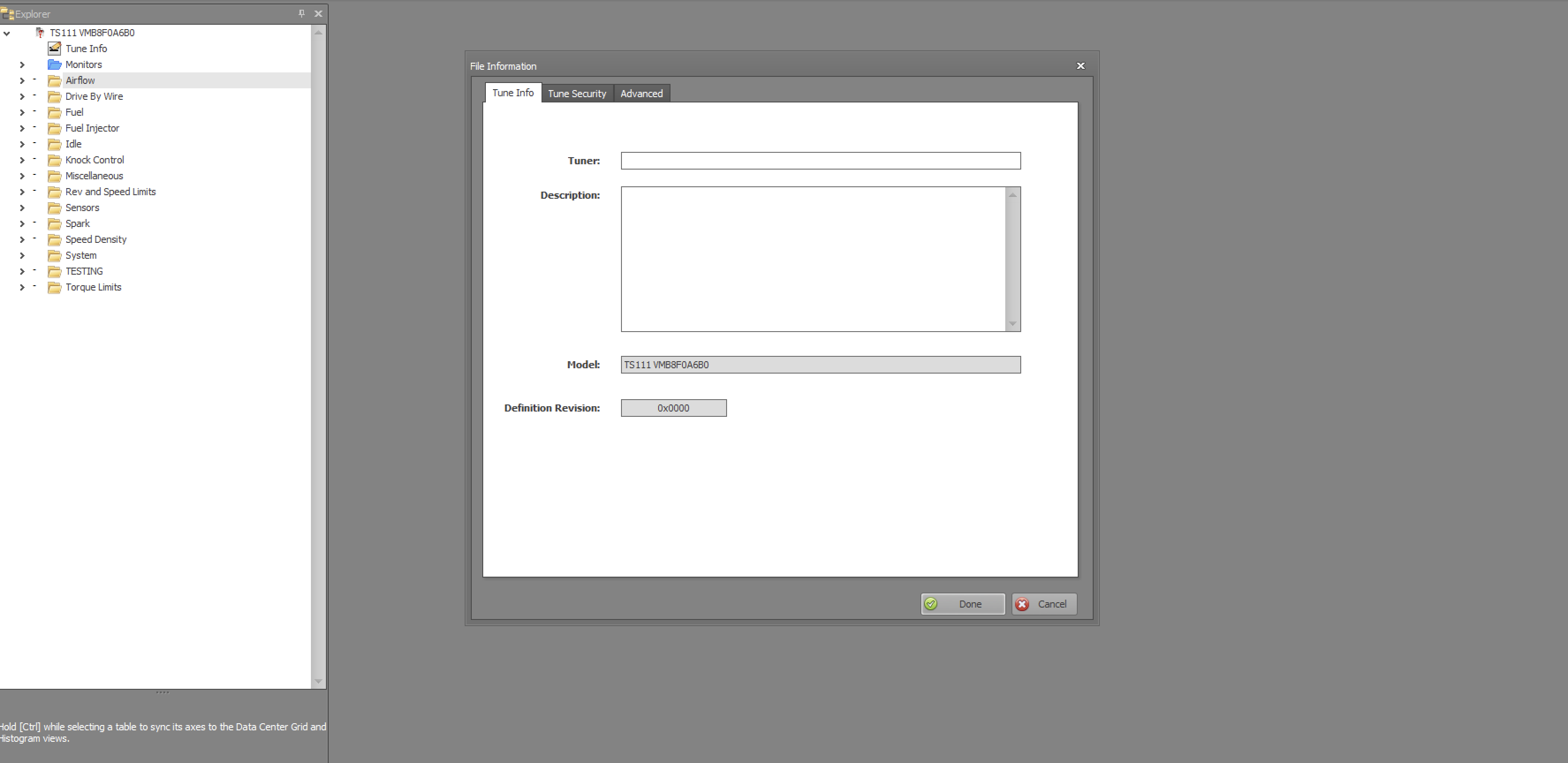
Selecting the Tune Info will bring up the following dialog.  This box helps you keep track of what you have done to the tune.  It is a good place to put what corrections you are making as well as any other tables that might be changed while you are tuning.

Tune Info

(Click on image to expand)

The dialog box has two other tabs...Tune Security and Advance.  The Tune Security tab allows you to assign a password to the tune as well as to lock it to any PV3 or PVCX GUID, with is an unique identifier for that device.  I suggest not to set that box, but certainly go ahead and assign a password if you wish.  Any tuning you do on your bike is specific to your bike and is your intellectual property.  Just remember that if you forget the password, then you are out of luck, there is no recovery for that situation.

The Advance tab will display the information on the STK file and other related information.  This screen is one that you usually never touch


The next item down the Tune Explorer list is the Monitor folder.  Selecting this shows the following:

Monitor

(Click on image to expand)

These are items to you view or monitor while connected to the bike and you are bringing data into Power Core Software Suite directly.  For our purposes, we will be ignoring this table.

This next table is very important but one of the least understood. The Mass Flow Through the Throttle Body is the only table in the Air Flow folder.

Mass Flow Through the Throttle Body

(Click on image to expand)

This table is very important for startups, for transitions between MAP stable points and most importantly if the MAP sensor fails.  In tuning talk, this is the Alpha-N table.  It strictly deals with the Throttle percent opening, the engine RPM, and what you think the air flow is through the throttle body.  Our engines do not have a Mass Air Flow sensor, so we have to tell the ECU what this value is at each cell point.  Most tuners I know either ignore this table or hit certain cells to fix a problem (like cold starting stability).  I have built an equation that deals with this table, but we will only deal with this table after we first gain a through understanding of tuning.

The Drive By Wire tables are in the Drive By Wire folder. For 2014 through 2018 Indian bikes, this is a very easy, straightforward set of curves.  With the introduction of the Drive Modes introduced in the 2019 TS111 & TS116 models as well as the FTR-1200 models it became a lot more complicated (to keep track of). The same principals apply to those models as we will discuss and show here, there are just more to keep track of.

Drive By Wire (DBW)

(Click on image to expand)

Under the folder labels Fuel are a lot of tables. The Component Protect tables I am not going to go through.  These are set by Polaris and only under very rare conditions would you need to change them.  Also, the EGT values are calculation value(s) from Modeled EGT table and not measured.  You have to take that at face value. 

The tables we will be extensively correcting are in the Individual Cylinder.  The Start Up Fuel and the Main Target AFR we set to obtain the operation parameters we want during and after tuning.  The Delay for fuel cut-off (Gear Change) is a useful value to help eliminate exhaust decal popping.  The rest of the tables I leave alone the majority of the time and I have no plans to discuss.

Fuel

(Click on image to expand)


Individual Cylinder

(Click on image to expand)

There are four tables under the individual cylinder folder.  These tables balance the fuel between front and rear cylinder and are vital to a smooth running well balanced engine.  Injector Compensation Factor Front and Rear tables make very minor changes, which I now usually do not correct.  They main tables for fuel balance are the IPW Comp tables Front and Rear.  These are the tables where we will spend the most time on. 

Main Target AFR

(Click on image to expand)

This table dictates the desired AFR (Air Fuel Ratio) that we want the engine to operate at under various loads and RPM.  This table is mis-understood by most beginning tuners.  The values you enter into this table mean nothing except for 14.7.  When you put the value of 14.7 into any cell, if operating in that cell (load and RPM match), then the ECU will operating in Closed-loop operation using the narrowband O2 sensors to maintain 14.7:1 exhaust AFR.  Another value in these cells and the ECU will attempt to meet that target AFR by performing calculations base on the many other tables that we will be tuning.  It is not a supervised AFR target like the 14.7 is.  So, you can really mess up the engine by going very lean by entering a value other than 14.7 if your fuel tables have not been properly corrected.  We will be discussing this further in future posts or through discussions on the Indian Motorcycles Net Forum.

The next folder deals with the Fuel Injector.  The tables we are interested in are the Injector Latency and Injector Scaling.   These table look like this:

Injector Latency

(Click on image to expand)

This table impacts starting and running under various battery voltage conditions.  I usually use the injector specs from performance supplies that have tested this.  If you are having trouble starting, changing the values in the lower voltage cells usually helps.

Injector Scaling

(Click on image to expand)

Injector scaling is very important if you change injectors to a different size.  This is a very easy value to calculate and is a ratio.  The three common sizes of injectors for our motorcycles is 280cc, 350cc, and 450cc.  The 280cc injector has been used on the 2014 through 2019 TS111 & TS116 bikes, Scouts and FTR's.  The 2020 and up move to 450cc injectors on the TS116 stage 2 kit.

The injection end angle table is a pretty intimidating table and should be left alone unless you are converting a tune from one checksum over to another or you are on a Dyno and throughly understand what this table does.

Injection End Angle

(Click on image to expand)

I do not plan to go through this table, if you have to touch this table, the Indian Motorcycle Net forum would be the best place for that discussion.  The rest of the table under the Fuel Injector should be left alone.

The next folder in the Tune Explorer tree is the Idle folder.  In the 2014 through 2018 models, it has three tables.  The 2019 and up TS111 & TS116 models and the FTR-1200 has more due to the extra drive modes available.

We will basically be touching two of the three tables, the Idle Speed and the Idle Speed 3d tables.

Idle Speed

(Click on image to expand)

Idle Speed 3d

(Click on image to expand)

The Idle Speed 3d table is a very important table to adjust the idle drop when downshifting and slowing down.  This was the source of a lot of behavioral issues in the first couple of years of Indians.

The next folder in the tree is the Knock Control.  I will not be going into an in-depth discussion with these tables, but will provide my guidelines on the one table I view beneficial in tuning.  That is the Max Knock Retard table.
Max Knock Retard

(Click on image to expand)

The next folder is the Miscellaneous.  This folder has the Engine Displacement table.  It is important to set your Engine Displacement correctly.  You can use this table to vary the overall tune up or down if you find you need a global correction.  Do not knock yourself out if it does not exactly equal your displacement.  I use it in a ratio way when I have to build a tune for a 118", 120", or 126".  Most of the time, you will not touch this value.

Engine Displacement

(Click on image to expand)

The next folder deals with speed and rev limits.  This is one area you have to be careful, yet should modify.  I will be providing my recommendations for these tables.  The tables of interest are: Rev Limit 1, Rev Limit by Gear, Rev Limit hysteresis, and the Speed limit per gear.  In newer models, these individual tables have been replaced by a single table array.  Makes changes easier.

Rev Limit 1

(Click on image to expand)


Just because we can raise the rev limit, does not mean it is a good idea.  Depending on the cam you are running, you will run out of power band way before the limit is reached.  Also, you must factor in the risk of engine damage due to over rev and design spec of rod and crank.

Rev Limit by Gear

(Click on image to expand)

This table sets the rev limit by gear.  I usually set this entire table to the Rev Limit 1 value.

Rev Limit Hysteresis

(Click on image to expand)

This is the bandwidth of where the rev limit kicks in and out.  I usually tighten this number.

Speed Limit per Gear

(Click on image to expand)

Just like the rev limit, just because you can set it up, should you and can the bike actually reach that speed?  Our bikes are basically limited per RPM ratios to 124 MPH iirc.  I have a spreadsheet that I built a while back that calculates the different speeds available depending on tire size, gear, and RPM of engine.  It is what it is.  Also, HP comes into play.  It takes a lot of power to push our bikes through the air and frankly, a stock or stage 2 TS111 is not going to exceed the overall speed limit of the gear/engine RPM train.

On newer calibration, the six tables have been combined into an array as shown below.

Speed Limit per Gear

(Click on image to expand)

You should never ever set this table above the rating of your tires.  I usually set it at 130 mph, which most bikes will never achieve unless on a Dyno.

Our next folder down the tree is Sensors.  Most calibrations contain the MAP folder.  The various settings include the sampling window, offset, slope, and min/max voltage.  We will not be touching these values except when we go to tune the Mass Flow through the Throttle Body table and we need to fail the MAP sensor.

Map Sensor Tables

(Click on image to expand)


The next folder down the tree is the Spark folder.  This folder contains the tables associated with the timing of the engine.  Polaris has chosen a very complicated method of timing.  It is the source of a lot of issues in engine performance when transitioning from idle to run.  I will get more in-depth on this subject as we start the tuning process.

Spark Folder

(Click on image to expand)

You can destroy an engine fairly quickly with bad timing settings.  Luckily we have Knock Control that provides some safe guard against this, though it is not fool proof.

The spark folder contains the Coil folder.  This folder has the dwell table for the coil.  You can make modifications to this table, but need to be careful or you could destroy your coil due to heat.  Some folks on the forum advocate a certain setting which we will explore when we get to this subject on tuning.

Coil Dwell

(Click on image to expand)

The next tables on the list are the timing tables.  The first and most important is the Ignition Timing 1(Primary) table.  This table comes into play almost all the time and is the one we are most interested in.

Ignition Timing 1 (Primary)

(Click on image to expand)

If you look at the notes for this table you will see how complicated this is:


If Primary Timing Active bit is equal to 1 (usual case when accelerating):

base timing target = Ignition Timing 1 Primary table minus knock retard (If vehicle equipped with knock sensor).


If Primary Timing Active bit is equal to 0, the ECU follows the following logic:


a = Ignition Timing table 2 plus Timing Table 2 Modifier by AFR, minus value from Ignition Timing 2 Scaling Array

b = Ignition Timing 1 Primary table minus Knock Control (If vehicle equipped with knock sensor).

c = Ignition Timing table 3 (or timing table 4 in rear cases)

d = minimum value from a and b


Base timing target = max value from c and d


After the base value is calculated, any temperature, tip-in, and/or per cylinder compensations are applied.


Final ignition timing targets are capped to a range of -36 to 54 degrees.


Quoting a very smart ECU engineer at Dynojet: "In general, primary timing is active when idle control is not active and you are not in decel. However, if there are issues, limits exceeded, etc then the ECU will kick out of Primary timing. There is no set threshold of any sort, it’s a pretty complex algorithm. I would not question “why Primary Timing is active”, but rather “why is it not active” if you ever see it is not. If you’re not in decel or idle, something is probably off.  


As for the other timing tables, timing 2 should really only be idle control.


Timing 3 is actually Minimum allowed timing for combustion and Timing 4 is Minimum allowed timing for heat. These tables are generally only active when in decel, but they are always checked to provide a floor for requested advance in the case of knock retard or other factors affecting base timing.”


So in summary, the timing should always be the Ignition Timing 1 (Primary) unless we are at idle or decel.  You can view data bit in the log file titled "Primary Timing Active bit" to make sure the Ignition Timing 1 (Primary) table is active.


Ignition Timing 2 is used during idle, but it gets more complicated since it also relies on the Timing Table 2 Modifier by AFR and Ignition Timing 2 Scaling array!


Ignition Timing 2

(Click on image to expand)

This table has the same notes of the Ignition Timing 1 (Primary) table.

Ignition Timing 2 Modifier by AFR

(Click on image to expand)

There are some things we need to look out for with this table.  I will discuss further as we get into tuning.  The notes for this table are:

Ignition Timing 2 Modifier by AFR


This table is only applied when Ignition Timing 2 is active.

Requested AF can never by leaner than 14.7, so the last 2 cells should never be hit unless the axis is re-scaled.


Requested AFR can never also never be richer than 6.2, so the cells lower than this will default to 6.2 if changed from stock.


Ignition Timing 2 Scaling Array


(Click on image to expand)

This array has 200 cells.  I have never had a good explanation as to what drives this array internally.  The notes for this table are:

This table is only applied when Ignition Timing 2 is active. The value from this table is subtracted from the Ignition Timing 2 table value.

Ignition 2 Scaling Index can be monitored to know which axis point the ECU is using.


Ignition Timing 3


(Click on image to expand)


Minimum allowed timing for combustion during deceleration

Ignition Timing 4

(Click on image to expand)

Minimum allowed timing for heat during deceleration


The next tables deal with modifying the timing per front & rear cylinder.  These can be used if knock is detected on one cylinder instead of both.  On the TS116, Polaris sets these tables extensively.  I am only going to show the front cylinder table as they are both the same.


Timing Modifier for Front Cylinder


(Click on image to expand)


The note for Front and Rear are:

Timing modifier for Front (or Rear) cylinder. Changes here will affect ignition timing for only the Front (or Rear) Cylinder.


Timing retard due to Engine temp and IAT


(Click on image to expand)

The notes for this table are:

Timing change due to Engine Temp and intake air temp.

Normally used to retard timing at high temp, some OEM strategies use this table to add timing at cold temps.

Positive values will add and negative values will remove timing (after the multiplier table is applied).


Timing retard due to Engine temp and IAT Multiplier


(Click on image to expand)


The notes for this table are:

This value is multiplied by the timing retard for high Engine Temp or intake air temp to get a final result for retard.

A value of 1 results in 100% of the value from the Engine Temp Retard table being applied.

A value of 0 results in NO retard being applied.


Timing retard due to tip-in tip-out


(Click on image to expand)

This table can help with sluggish throttle response.  The notes for this table are:

Timing retard for knock prevention due to throttle tip-in/tip-out


The next folder down the tree is one of the most important, Speed Density folder.  In this folder we find the Volumetric Efficiency and the Volumetric Efficiency change from air pulsation.


Volumetric Efficiency


(Click on image to expand)


This is the table, with the IPW Comp tables that my equation will be working on.  In a speed density system, this is the most important table and provides the mode of the engine ability to move air through the engine at various loads and RPM.  If you have this table modeled correctly, then the ECU can make accurate calculations to hit the Target AFR table value.

Volumetric Efficiency change from air pulsation

(Click on image to expand)

This is a useful table when converting tunes from one Tune CMP or Checksum to another.  I usually do not modify otherwise.

The next folder down the tree is the System folder.  In this folder you will find the Misfire Monitor folder.  There are tables in this folder that when modify go a long way in preventing the spurious mis-fires that our Indians tend to throw.

Misfire Monitor

(Click on image to expand)

I usually set these tables to equal other Tune CMP calibrations that have more stable engine misfire detection.  The last table, Time for Misfire Detection After Start is very useful to change to stop all the misfire codes during starting that we get on some bikes.  I usually set this for 120 seconds.

Time for Misfire Detection After Start

(Click on image to expand)


The last folder down the tree is the Torque Limits.  Depending on the Tune CMP, there will be a few to many tables.  These tables will limit your torque output of the engine under certain conditions.  It is easy to forget that our engine management system calculates the required torque demanded on the engine at any one time.  I usually just max out the values or set them high so they don't come into play.

Torque Limit

(Click on image to expand)

Load Request Ceiling 01

(Click on image to expand)


This concludes our overview of the components in a tune.  The next post will be setting up the method for tuning and recording our first set of logs to make fuel corrections.