This post will describe the different aspects of the Indian tune. It is a short guide to the tables that we have access to and the main tables we will change for tuning.
Open the C3 module in the Power Core Software Suite's Application Launcher windows. Once it is opened, select the folder icon to open a tune. In this case, we are going to open your STK file. The following is the window you should get. (Note, I have reduced screen clutter by configuring my desktop not to have the gauges that are displayed on the right-hand side of the C3 module).
C3 Module with an Opened STK file
What you see is the essences of a tune. The tree on the left-hand side are a visible organization of the tables we will use to modify our tune, it is called Explorer. Think of it as the Tune Explorer as Windows has the File Explorer. The top left-hand window is the current tune(s) we have opened and can perform task on.
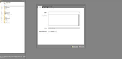
Selecting the Tune Info will bring up the following dialog. This box helps you keep track of what you have done to the tune. It is a good place to put what corrections you are making as well as any other tables that might be changed while you are tuning.
Tune Info
The dialog box has two other tabs...Tune Security and Advance. The Tune Security tab allows you to assign a password to the tune as well as to lock it to any PV3 or PVCX GUID, with is an unique identifier for that device. I suggest not to set that box, but certainly go ahead and assign a password if you wish. Any tuning you do on your bike is specific to your bike and is your intellectual property. Just remember that if you forget the password, then you are out of luck, there is no recovery for that situation.
The Advance tab will display the information on the STK file and other related information. This screen is one that you usually never touch
The next item down the Tune Explorer list is the Monitor folder. Selecting this shows the following:
Monitor
These are items to you view or monitor while connected to the bike and you are bringing data into Power Core Software Suite directly. For our purposes, we will be ignoring this table.
This next table is very important but one of the least understood. The Mass Flow Through the Throttle Body is the only table in the Air Flow folder.
Mass Flow Through the Throttle Body
This table is very important for startups, for transitions between MAP stable points and most importantly if the MAP sensor fails. In tuning talk, this is the Alpha-N table. It strictly deals with the Throttle percent opening, the engine RPM, and what you think the air flow is through the throttle body. Our engines do not have a Mass Air Flow sensor, so we have to tell the ECU what this value is at each cell point. Most tuners I know either ignore this table or hit certain cells to fix a problem (like cold starting stability). I have built an equation that deals with this table, but we will only deal with this table after we first gain a through understanding of tuning.
The Drive By Wire tables are in the Drive By Wire folder. For 2014 through 2018 Indian bikes, this is a very easy, straightforward set of curves. With the introduction of the Drive Modes introduced in the 2019 TS111 & TS116 models as well as the FTR-1200 models it became a lot more complicated (to keep track of). The same principals apply to those models as we will discuss and show here, there are just more to keep track of.
Drive By Wire (DBW)
Under the folder labels Fuel are a lot of tables. The Component Protect tables I am not going to go through. These are set by Polaris and only under very rare conditions would you need to change them. Also, the EGT values are calculation value(s) from Modeled EGT table and not measured. You have to take that at face value.
The tables we will be extensively correcting are in the Individual Cylinder. The Start Up Fuel and the Main Target AFR we set to obtain the operation parameters we want during and after tuning. The Delay for fuel cut-off (Gear Change) is a useful value to help eliminate exhaust decal popping. The rest of the tables I leave alone the majority of the time and I have no plans to discuss.
Fuel
Individual Cylinder
There are four tables under the individual cylinder folder. These tables balance the fuel between front and rear cylinder and are vital to a smooth running well balanced engine. Injector Compensation Factor Front and Rear tables make very minor changes, which I now usually do not correct. They main tables for fuel balance are the IPW Comp tables Front and Rear. These are the tables where we will spend the most time on.
Main Target AFR
This table dictates the desired AFR (Air Fuel Ratio) that we want the engine to operate at under various loads and RPM. This table is mis-understood by most beginning tuners. The values you enter into this table mean nothing except for 14.7. When you put the value of 14.7 into any cell, if operating in that cell (load and RPM match), then the ECU will operating in Closed-loop operation using the narrowband O2 sensors to maintain 14.7:1 exhaust AFR. Another value in these cells and the ECU will attempt to meet that target AFR by performing calculations base on the many other tables that we will be tuning. It is not a supervised AFR target like the 14.7 is. So, you can really mess up the engine by going very lean by entering a value other than 14.7 if your fuel tables have not been properly corrected. We will be discussing this further in future posts or through discussions on the Indian Motorcycles Net Forum.
The next folder deals with the Fuel Injector. The tables we are interested in are the Injector Latency and Injector Scaling. These table look like this:
Injector Latency
The next folder is the Miscellaneous. This folder has the Engine Displacement table. It is important to set your Engine Displacement correctly. You can use this table to vary the overall tune up or down if you find you need a global correction. Do not knock yourself out if it does not exactly equal your displacement. I use it in a ratio way when I have to build a tune for a 118", 120", or 126". Most of the time, you will not touch this value.
Engine Displacement
The next folder deals with speed and rev limits. This is one area you have to be careful, yet should modify. I will be providing my recommendations for these tables. The tables of interest are: Rev Limit 1, Rev Limit by Gear, Rev Limit hysteresis, and the Speed limit per gear. In newer models, these individual tables have been replaced by a single table array. Makes changes easier.
Rev Limit 1If Primary Timing Active bit is equal to 1 (usual case when accelerating):
base timing target = Ignition Timing 1 Primary table minus knock retard (If vehicle equipped with knock sensor).
If Primary Timing Active bit is equal to 0, the ECU follows the following logic:
a = Ignition Timing table 2 plus Timing Table 2 Modifier by AFR, minus value from Ignition Timing 2 Scaling Array
b = Ignition Timing 1 Primary table minus Knock Control (If vehicle equipped with knock sensor).
c = Ignition Timing table 3 (or timing table 4 in rear cases)
d = minimum value from a and b
Base timing target = max value from c and d
After the base value is calculated, any temperature, tip-in, and/or per cylinder compensations are applied.
Final ignition timing targets are capped to a range of -36 to 54 degrees.
As for the other timing tables, timing 2 should really only be idle control.
Timing 3 is actually Minimum allowed timing for combustion and Timing 4 is Minimum allowed timing for heat. These tables are generally only active when in decel, but they are always checked to provide a floor for requested advance in the case of knock retard or other factors affecting base timing.”
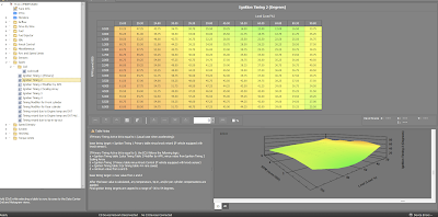
So in summary, the timing should always be the Ignition Timing 1 (Primary) unless we are at idle or decel. You can view data bit in the log file titled "Primary Timing Active bit" to make sure the Ignition Timing 1 (Primary) table is active.
Ignition Timing 2 is used during idle, but it gets more complicated since it also relies on the Timing Table 2 Modifier by AFR and Ignition Timing 2 Scaling array!
Ignition Timing 2 Modifier by AFR
This table is only applied when Ignition Timing 2 is active.
Requested AF can never by leaner than 14.7, so the last 2 cells should never be hit unless the axis is re-scaled.
Requested AFR can never also never be richer than 6.2, so the cells lower than this will default to 6.2 if changed from stock.
Ignition Timing 2 Scaling Array
This table is only applied when Ignition Timing 2 is active. The value from this table is subtracted from the Ignition Timing 2 table value.
Minimum allowed timing for heat during deceleration
The next tables deal with modifying the timing per front & rear cylinder. These can be used if knock is detected on one cylinder instead of both. On the TS116, Polaris sets these tables extensively. I am only going to show the front cylinder table as they are both the same.
Timing Modifier for Front Cylinder
The note for Front and Rear are:
Timing modifier for Front (or Rear) cylinder. Changes here will affect ignition timing for only the Front (or Rear) Cylinder.
Timing retard due to Engine temp and IAT
Timing change due to Engine Temp and intake air temp.
Normally used to retard timing at high temp, some OEM strategies use this table to add timing at cold temps.
Positive values will add and negative values will remove timing (after the multiplier table is applied).
Timing retard due to Engine temp and IAT Multiplier
The notes for this table are:
This value is multiplied by the timing retard for high Engine Temp or intake air temp to get a final result for retard.
A value of 1 results in 100% of the value from the Engine Temp Retard table being applied.
A value of 0 results in NO retard being applied.
Timing retard due to tip-in tip-out
Timing retard for knock prevention due to throttle tip-in/tip-out
The next folder down the tree is one of the most important, Speed Density folder. In this folder we find the Volumetric Efficiency and the Volumetric Efficiency change from air pulsation.
Volumetric Efficiency


